-
Notifications
You must be signed in to change notification settings - Fork 0
Software Documentation
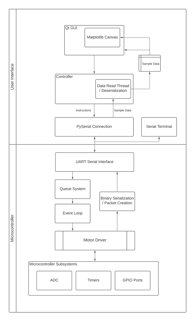
The software consists of two main parts, software for the embedded microcontroller that executes instructions, moves the stage and reads / collects data, and the pyQt5 graphical user interface which sends instructions to and receives data from the microcontroller.

The roll of the queue system to store the instructions and data that are received through the UART serial connection and then feed these instructions into the event loop. It acts as a buffer, ensuring that instructions are reliably captured, executed in order and gives the program the ability communicate with the client serial connection asynchronously.
The queue system contains two separate queue object instances. The first is the program queue which has the job of capturing instructions for temporary storage so they're only executed when instructed. This ensures that a list of instructions can be sent to the microcontroller before any execution occurs.
The second is the main queue which is directly tied to the event loop such that if an instruction is added to the queue whilst idle, then it will be executed immediately, so instructions may be executed before the next has been loaded into the queue.
Entering instructions into the program or main queue can be controlled using the start program (M00) and end program (M03) instructions. (All QtPy GUI function use the start and end program instructions.)
The length of both queues by default are set to 300 items with an instruction size of 50 characters. Both values can be updated in the queue header file. This means that at most 300 instructions can be stored on the microcontroller before the queue begins to overwrite itself. The queue uses a fixed amount of memory and cycles back to the start of the queue so instructions can be added indefinitely within it's memory bounds.
- Enqueue: Adds an item to the end of the queue
- Dequeue: Removes the first item on the queue
- Peek: Returns the first item on the queue
- Print To Serial: Writes all items within the queue to the serial connection from front to rear.
- Get: Returns a item at a specific index
- Clear: Dequeues every item from front to rear.
Each instruction is stored within the queue as the string that was received from the client. A valid instruction contains the Gcode instruction followed by the instructions accompanying parameters where the instruction and parameters are all spaced separated.
G01 X10 Y35 Z55
S1 8
T1
Most instructions are added to the queue, parsed and executed within the event loop but state instructions are executed prior to being added to the queue. This is because these function operate outside of the scope of the queue / event loop.
M00 tells the microcontroller to load the forthcoming instructions within the program queue until it receives a M03 instruction. The program queue will then load all it's instructions into the main queue.
M01 stops the current execution of the queue and waits to receive a M02 instruction to resume execution. Stopping execution doesn't dequeue the current instruction. So as long as the current state of execution is saved, execution will resume where it had left off.
Our implementation of the event loop is just like any other event loop design pattern. At each loop iteration the queue is checked to see if it's empty. Each item is then parsed into an instruction struct object by splitting the string into its constituent parts, delimited by spaces. The first word is set to the instruction field while the remainder are split into an array of parameters both using char arrays as the underlying type.
The instruction is then compared against a known set of strings and the parameters are cast to the expected data type for the function call to execute the instruction.
The Qt GUI uses the PySerial library as a dependency for serial communication with the microcontroller. The microcontroller receives instructions and sends sampling data using an interrupt driven UART connection. By default the connection uses the configuration:
baudrate: 115 200 bps
bytesize: 8 bits
parity: odd
stopbits: 2
timeout: 200
Using the baudrate of 115,200 bps reduced the frequency of transmission errors compared to 57,600 bps.
-
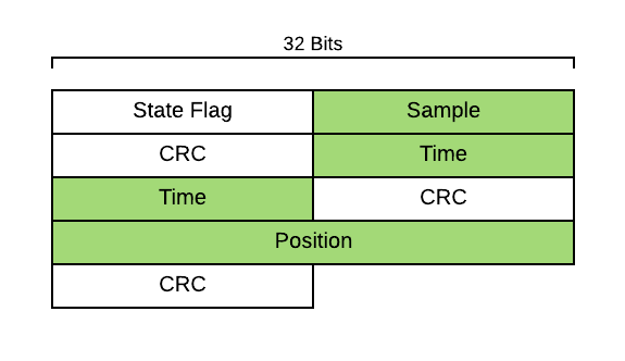
For each sample of data collected when send 7 pieces of information, the sample flag, the sample value, time, position and crc values for all sample data values.
-
The ordering of bits and byte arrays use big endian order.

There are 3 state flags that are used to indicate to the GUI what to expect from the received data and set it's current state property. This includes sample data, idle (tells the gui not to expect more data and is the default state), and calibration.
- 0xFF 0xFF - Sampling Data
- 0xFF 0xFE - Idle
- 0xFF 0xFD - Stationary Sampling
- 0xFF 0xFC - Calibration
These state flags are formatted to use 16 bits and start with 0xFF to allow differentiation between incoming ADC 12 bit data, thus it is impossible to send values above 0x0FFF.
All data sent over the serial connection is sent as 8 bits at a time due to the limitations of UART. Thus, each piece of data is serialized into an array of bytes where sample values are 16 bits, and floats like time and position are 32 bits. Once read by the GUI they're then reconstructed into their original data types.
To be able to detect transmission errors, ensuring that data is sent accurately and reliably, a crc 16 bit error checking code is sent with all int and float data packets. The code is calculated on the array of bytes for each data type and sent as a short data type to the GUI.
We use a table driven, software implementation of crc error checking with the pycrc python library. It's docs can be found here.
The default polynomial used is a 0x8005, which has reflect-in and reflect-out set to true so that the input message and checksum are reflected for the purpose of better algorithm efficiency.
The motor driver class maintains the state of the stage, including; its current position, sample duration, stepsPerMM (calculated during calibration), motor step delay, total time elapsed (for scan between operations), step mode, and averaging interval. During execution and where relevant, these state variables are updated and maintained so that execution can behave smoothly between operations.
Calibration works by stepping to the limit switch connected to the B2 port. Once the switch to turn on, the direction is changed and every step back to the B1 port switch is counted. Based on the hardcoded length of the stage, this is used to calculate the number of steps per millimeter. This then allow us to make the unit conversion from milimeters on the GUI to the number of required steps to reach the desired position.
The stage has two ways of moving using the G00 and G01 instructions see instructions. If ADC is turned on, then the stage will use the scan between method of movement. This means that the stage will move by the step length variable's value and pause to collect ADC data before moving to the next sampling position.
Currently motor speed is constant at the maximum motor speed between samples and movement to new positions. With the use of G01, it's possible to improve functionality by adding a new function to set the motor speed and change the motor step timer to move at different rates.
Before a scan between operation can be executed, the stage offsets it's postion a certain amount of steps from the starting position. This avoids play within the steper motor as the stepper motor changes direction, which could potentially give inaccurate postion and sample values. Once at the offset position, the stage will then move in the direction of the start position and begin collecting data once it has reached the starting position.
This function takes longer duration samples at individual positions along the stage route, reducing the impact of noise and outliers on the averaged samples.
-
Using a scan between configuration of both low sample duration and low step length between samples begins to reach the limits of how quickly the Qt GUI can keep up with the number of packets being received and processed. This is due to the pipeline of reading data from the buffer, completing crc remainder values, reconstructing it into it's respective data type and saving data to the sample data model. This results in the data visually falling behind from the microcontroller when plotting on the matplotlib canvas. This isn't a significant issue because data isn't lossed unless the distance for a "scan between" is long. This is the point when the receive buffer is overun. The issue can be alleviated by increasing the buffer size with the pyserial set_buffer_size method.
-
In the best case scenario, if our baudrate is 115, 200 bps and the number of bits that's sent for each data packet is 180 bits, then we can expect that the maximum number of data packets that we sent per second is 640.