- Calibration and notes
- How to use the firmware
- See the pics folder for more pictures
$ git clone
$ cd project/LightMeterV2
$ pio lib install
$ pio run
$ pio run --target upload
Notes: The TSL25x1 lib I use is either custom, or hacked from anoter one. We setup the sensor and powerup on setup(), then let it run freely.
The sensor do it's integration time by itself, we NEVER poweroff the sensor, then we read the value as the loop loops.
This is done to avoid the 120ms*integrationTime etc. delay, the loop is ultra fast, then buttons are reactive.
And we can then set the sensor to a high integration value without having 500ms delay introduced in the loop.
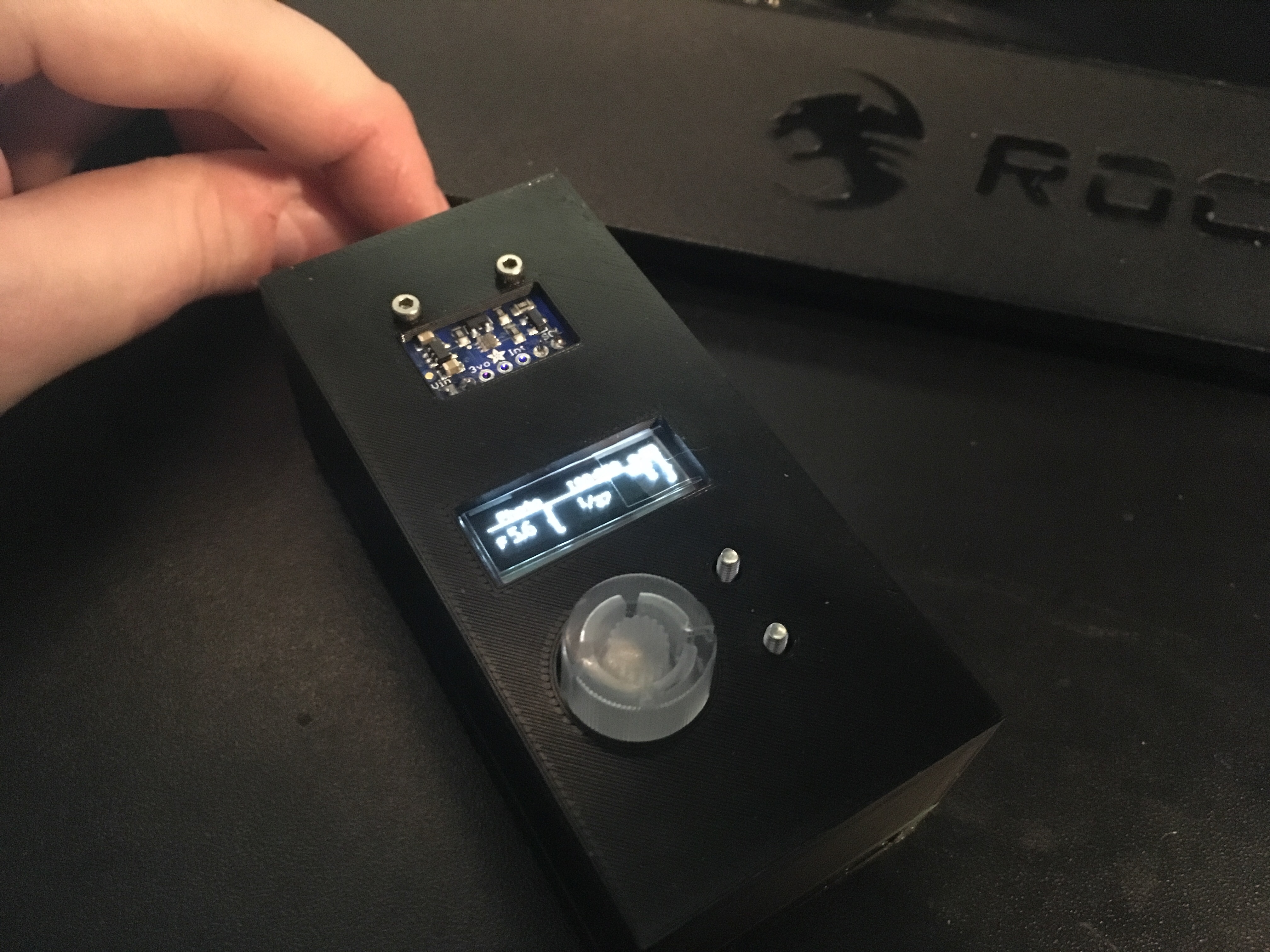
The Light Meter isn't super slim, but not too big, it could get 5mm less easily if the pins connecting the teensyview were trimmed.
Without trimming everything used is stock without modifications. Also the OLED display PCB is way bigger than the LCD itself, and that forbig to reduce by ~3mm without having an ugly PCB popping out. Trimming the pins will be envisaged in the future.
The choosen battery was a BL-5C because I have one spare, but any with a JST connector would do the job, only the middle part and bottom of the enclosure would need redesign. The battery connector is some sort of wire bended, passed through a hole and glued after soldering. Not the best but I didn't wanted to wait a month to get a small 3-pins 3mm pitch battery connector to design the enclosure.
The stock BL-5C, genuine, is a 1000mAh battery, the Light Meter, with sensor free-running is consuming about 40mA according to the battery charger, which allows between 17 and 25 hours of continus running, in theory. You can still easily swap battery anyway, just bring the right screwdriver, and spare charged batteries with you.
The USB data is hard wired between the D+/D- pads of the teensy to the battery babysitter, allowing to program the teensy from the battery charger directly without doing anything, reset button is useless as we are using the stock teensy bootloader, permitting remote flash and reboot.
The TSL2591 doesn't permit changing I2C address, you can only have one.
- Design some sort of sliding window to protect the sensor
- Games, because why not ?
Uses the following:
- Teensy 3.2
- TeensyView (ALTERNATE mode)
- TSL2591 HDR Light Sensor
- Battery Babysitter
- Rotary Encoder with Red/Green led
- Knob, transparent
- Battery: BL-5C (1000mAh nokia battery)
- Mini switch: 6mm push button
- Diode: 1N4148
- Transistor: 2N3940, TO-92
- Resistor: 4.7k
- Capacitor: 10uF, radial, polarised
- A PCB from the PCB folder
Some build notes :
- The battery can be either connected from the JST connector (DIY enclosure) or from the pads right next to it (provided enclosure)
- The D+ and D- from USB should be soldered on the teensy first before soldering it to the PCB, make sure to mark with a marker the D- wire. Then after soldering the teensy and the babysitter, twist the two DATA wires and solder them accordingly to the babysitter very small pads.
- The TSL2591 use four wire (Vcc, GND, SDA, SCL) and ideally use two small connectors, allowing for quick disconnect, for either hacking or easy replacement.
- The TeensyView needs to be in ALTERNATE mode, cut some jumper pads and solder the others before sticking the OLED glass. Look at Sparkfun docs for that part.
- The Alternate mode is unfortunately needed because of the pins 10 & 11 which are already used for the RED and Green LEDs. A next revision can change that.
- The TeensyView pins are connected by using standard "long" headers, see
pics/main_pcb_battery_babysitter.jpgfor soldering. Also you will have to trim the headers by 5mm on top, to make the display closed to the teensy. - You have to put the battery babysitter switch to the OFF position, or it will override the power-on/off feature.
Schematic diagram. Click to enlarge.
3D designed, printed, works great, to be published.
An assembly
- Use libraries:
- https://github.com/XenGi/teensy.pretty
- https://github.com/XenGi/teensy_library
- RGB Encoder Footprint and Library from https://github.com/sparkfun/Rotary_Encoder_Breakout-Illuminated
Uses code from:


